In materials science, the strength of a material is
its ability to withstand an applied load without failure. A load applied to a
mechanical member will induce internal forces within the member called stresses
when those forces are expressed on a unit basis. The stresses acting on the
material cause deformation of the material in various manner. Deformation of
the material is called strain when those deformations too are placed on a unit
basis. The applied loads may be axial (tensile or compressive), or shear. The
stresses and strains that develop within a mechanical member must be calculated
in order to assess the load capacity of that member. This requires a complete
description of the geometry of the member, its constraints, and the loads
applied to the member and the properties of the material of which the member is
composed. With a complete description of the loading and the geometry of the
member, the state of stress and of state of strain at any point within the
member can be calculated. Once the state of stress and strain within the member
is known, the strength (load carrying capacity) of that member, its
deformations (stiffness qualities), and its stability (ability to maintain its
original configuration) can be calculated. The calculated stresses may then be
compared to some measure of the strength of the member such as its material
yield or ultimate strength. The calculated deflection of the member may be
compared to a deflection criteria that is based on the member's use. The
calculated buckling load of the member may be compared to the applied load. The
calculated stiffness and mass distribution of the member may be used to
calculate the member's dynamic response and then compared to the acoustic
environment in which it will be used.
Material strength refers to the point on the
engineering stress–strain curve (yield stress) beyond which the material
experiences deformations that will not be completely reversed upon removal of
the loading and as a result the member will have a permanent deflection. The
ultimate strength refers to the point on the engineering stress–strain curve
corresponding to the stress that produces fracture.
The
following are basic definitions and equations used to calculate the strength of
materials.
Stress
(normal)
Stress is
the ratio of applied load to the cross-sectional area of an element in tension
and is expressed in pounds per square inch (psi) or kg/mm2.
Load
|
L
|
|||
Stress, σ
|
=
|
=
|
||
Area
|
A
|
Strain
(normal)
A measure
of the deformation of the material that is dimensionless.
change in length
|
Δ L
|
|||
Strain, ε
|
=
|
=
|
||
original length
|
L
|
|||
Stress
Strain Curve
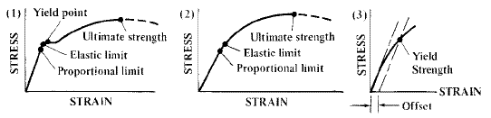
Proportional limit is the point on a stress-strain
curve at which it begins to deviate from the straight-line relationship between
stress and strain. See accompanying figure at (1 & 2).
Elastic limit is the maximum stress to which a
specimen may be subjected and still return to its original length upon release
of the load. A material is said to be stressed within the elastic region when
the working stress does not exceed the elastic limit, and to be stressed in the
plastic region when the working stress does exceed the elastic limit. The
elastic limit for steel is for all practical purposes the same as its
proportional limit. See accompanying figure at (1, 2).
Yield point is a point on the stress-strain curve at which
there is a sudden increase in strain without a corresponding increase in
stress. Not all materials have a yield point. See accompanying figure at (1).
Yield strength, Sy, is the maximum
stress that can be applied without permanent deformation of the test specimen.
This is the value of the stress at the elastic limit for materials for which
there is an elastic limit. Because of the difficulty in determining the elastic
limit, and because many materials do not have an elastic region, yield strength
is often determined by the offset method as illustrated by the accompanying
figure at (3). Yield strength in such a case is the stress value on the
stress-strain curve corresponding to a definite amount of permanent set or
strain, usually 0.1 or 0.2 per cent of the original dimension.
Modulus of elasticity
Metal deformation is proportional to the imposed
loads over a range of loads.
Since stress is proportional to load and strain is
proportional to deformation, this implies that stress is proportional to
strain. Hooke's Law is the statement of that proportionality.
Stress
|
σ
|
|||
=
|
=
|
E
|
||
Strain
|
ε
|
|||
The constant, E, is the modulus of
elasticity, Young's modulus or the tensile modulus and is the material's
stiffness. Young's modulus is in terms of 106 psi or 103 kg/mm2.
If a material obeys Hooke's Law it is elastic. The modulus is insensitive to a
material's temper. Normal force is directly dependent upon the elastic modulus.
Proportional
limit
The
greatest stress at which a material is capable of sustaining the applied load
without deviating from the proportionality of stress to strain. Expressed in
psi (kg/mm2).
Ultimate strength (tensile)
The
maximum stress a material withstands when subjected to an applied load.
Dividing the load at failure by the original cross sectional area determines
the value.
Elastic limit
The point
on the stress-strain curve beyond which the material permanently deforms after
removing the load.
Yield strength
Point at which material exceeds the elastic limit
and will not return to its origin shape or length if the stress is removed.
This value is determined by evaluating a stress-strain diagram produced during
a tensile test.
Poisson's ratio
The ratio
of the lateral to longitudinal strain is Poisson's ratio for a given material.
lateral strain
|
|||
µ
|
=
|
||
longitudinal strain
|
|||
Poisson's
ratio is a dimensionless constant used for stress and deflection analysis of
structures such as beams, plates, shells and rotating discs.
Aluminium
|
0.334
|
Nickel silver
|
0.322
|
Beryllium copper
|
0.285
|
Phosphor bronze
|
0.349
|
Brass
|
0.340
|
Rubber
|
0.500
|
Cast iron, grey
|
0.211
|
Steel, cast
|
0.265
|
Copper
|
0.340
|
high carbon
|
0.295
|
Inconel
|
0.290
|
mild
|
0.303
|
Lead
|
0.431
|
nickel
|
0.291
|
Magnesium
|
0.350
|
Wrought iron
|
0.278
|
Monel metal
|
0.320
|
Zinc
|
0.331
|
Bending stress
When bending a piece of metal, one surface of the
material stretches in tension while the opposite surface compresses. It follows
that there is a line or region of zero stress between the two surfaces, called
the neutral axis. Make the following assumptions in simple bending theory:
- The beam is initially straight, unstressed and symmetric
- The material of the beam is linearly elastic, homogeneous and isotropic.
- The proportional limit is not exceeded.
- Young's modulus for the material is the same in tension and compression
- All deflections are small, so that planar cross-sections remain planar before and after bending.
Using
classical beam formulas and section properties, the following relationship can
be derived:
3PL
|
||
Bending stress, σb
|
=
|
|
2wt2
|
||
PL3
|
||
Bending or flexural modulus, Eb
|
=
|
|
4wt3y
|
||
Where:
|
P
|
=
|
normal
force
|
l
|
=
|
beam
length
|
|
w
|
=
|
beam
width
|
|
t
|
=
|
beam
thickness
|
|
y
|
=
|
deflection
at load point
|
The
reported flexural modulus is usually the initial modulus from the stress-strain
curve in tension.
The
maximum stress occurs at the surface of the beam farthest from the neutral
surface (axis) and is:
Mc
|
M
|
|||
Max surface stress, σmax
|
=
|
=
|
||
I
|
Z
|
|||
Where:
|
M
|
=
|
bending
moment
|
c
|
=
|
distance
from neutral axis to outer surface where max stress occurs
|
|
I
|
=
|
moment
of inertia
|
|
Z
|
=
|
For a
rectangular cantilever beam with a concentrated load at one end, the maximum
surface stress is given by:
3dEt
|
||
σmax
|
=
|
|
2l2
|
||
The methods
to reduce maximum stress are to keep the strain energy in the beam constant
while changing the beam profile. Additional beam profiles are trapezoidal,
tapered and torsion.
Where:
|
d
|
=
|
deflection
of the beam at the load
|
E
|
=
|
Modulus
of Elasticity
|
|
t
|
=
|
beam
thickness
|
|
l
|
=
|
beam
length
|
Yielding
Yielding occurs when the design stress exceeds the
material yield strength. Design stress is typically maximum surface stress
(simple loading) or Von Mises stress (complex loading conditions). The Von
Mises yield criterion states that yielding occurs when the Von Mises stress, 
 exceeds the yield strength
in tension. Often, Finite Element Analysis stress results use Von Mises
stresses.
exceeds the yield strength
in tension. Often, Finite Element Analysis stress results use Von Mises
stresses.
exceeds the yield strength
in tension. Often, Finite Element Analysis stress results use Von Mises
stresses.
Safety
factor is a function of design stress and yield strength. The following
equation denotes safety factor, fs.
YS
|
||
fs
|
=
|
|
DS
|
||
Where YS
is the Yield Strength and DS is the Design Stress

